In an industry where every detail matters, understanding the basics of camber and flatness is vital. Many people assume that the two terms are synonymous but this is a dangerous misconception. We have answered a few key questions which should help you to better grasp the concepts.

What is Camber?
Camber is the measurement of a substrate’s curvature on both faces showing the deviation, bow and warp along the longest linear dimension. This is normally measured using a set of parallel plates with a gap that the substrates will pass through. If the part can’t slide through, the camber is outside of specifications. It is most often specified in inch per inch specifications.
What does camber look like?
Ideally a part with perfect camber would be completely uniform in thickness and would lay flat against a surface without restraint.

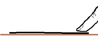
Bad camber is typically the result of deviation, which is the bow and warp of a substrate. One example of poor camber is if you press down on one corner of a part with a flat face and the other corners lift up.

A part that has flat faces but the thickness is not uniform, is another example of bow and warp. This may not be visible to the naked eye.

How is camber measured?
Substrates are inspected for camber using two ground, parallel plates spaced at a fixed distance by the following formula explained by Coorstek:
D = T + (C x L) where:
D = The camber distance setting
T = Substrate mode of thickness, where the mode is defined as the value most frequently measured
C = Camber value (reference part drawing)
L = Substrate length or longest outside dimension
Substrate mode of thickness, T, is established using an .080” diameter anvil micrometer. The thickness of each sample piece is measured to the nearest .0005” at any point away from the edge. The measured values are plotted until a mode of thickness value is determined.
Example: For a nominal 4.0” x 3.5” x .025” substrate:
Measured mode of thickness, T = .0255”
Camber value, C = .003 in. / in.
Maximum outside dimension, L = 4.0”
Maximum camber allowed: D = .0255” + (.003 in./in. x 4.0”) = .0375”
Parallel plates method for measuring camber:
To inspect for camber, parallel plates are set at a 45° angle with a gap equal to the “D” value determined in the formula. Substrates that pass through the gap under their own weight are acceptable (Coorstek).
Test indicator method for measuring camber:
A test indicator sitting on a calibrated granite table is placed on the part and zeroed out to the piece. The test indicator slides diagonally from one corner to another, measuring the difference from the zeroed value to the positive and negative values, and is then equated by total variation. This is done on both sides of the substrate. The test indicator method can be used to measure both the restrained and unrestrained states. In order to measure the unrestrained state, the part is placed on a piece of acid free paper allowing the part to move freely without ringing down to the granite table. Ringing down occurs when the part appears to be under vacuum and is suctioned to the table, which is the method of measuring the part in the restrained state.
The difference between the two methods:
The parallel plate method allows a fast and economic way to assure that parts meet the camber specification using a Go, Don’t Go (pass/fail) method. The test indicator method provides the actual camber of said part. However, the extended time required to perform the test indicator method results in increased cost.
What is flatness?
Flatness is the measurement of a single plane showing the deviation of the part from one point to another point. This is measuring the peak to valley of that face. For example, it is possible to have an extremely flat face on a wedge shaped part. That being said, a part may have a flat face with poor camber.
What does flatness look like?
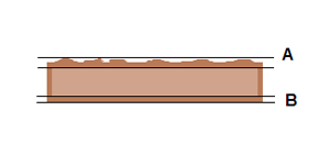
Notice how face A on the image below deviates with many peaks and valleys, whereas face B has no deviations. Face B is flat and A is not.

The definition of flatness addresses individual faces, meaning that the substrate or part as a whole may not be parallel. Let’s look at the classic table example.
The first image below illustrates a perfectly flat table. The center image is the same flat table with one leg removed. The third image shows that table forming a wedge shape when resting on the ground. The table top still has a flat face despite the new shape. While all 3 parts have flat faces, not all 3 are parallel.


How should you word a request for flatness and camber specifications?
When placing a request for flat and parallel parts there are two components you must address. First, specify a thickness tolerance of +/- whatever is required. Second, attach a statement dictating “flat and parallel” to a given specification. A camber specification should be made in addition to this request in order to control bow and warp.
What is a typical substrate's camber specification?
A typical substrate in as fired condition has a camber specification of .002’’ to .003’’ inch per inch. A lapped or polished substrate will have camber of .0005”/”.
It is necessary to understand that stress is induced as you remove stock equally from both sides. With that said, the length, width and the thickness are critical factors in determining the substrates potential. Often this will be specified in the restrained state on parts .015” thick or thinner. Restrained state means under vacuum or with pressure applied to hold the part down on a flat surface.
At Centerline we have trained machinists who are experts in providing you with the right finish. If you or your customers have any further questions please feel free to call 978-568-1330, email technical support or  .
.


